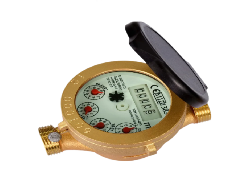
Multi-jet Liquid-sealed Water Meter
Multi-jet Liquid-sealed Water Meter
Multi-jet Liquid-sealed Water Meter
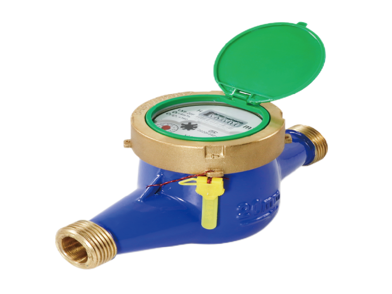
Dimension Diagram (Horizontal)

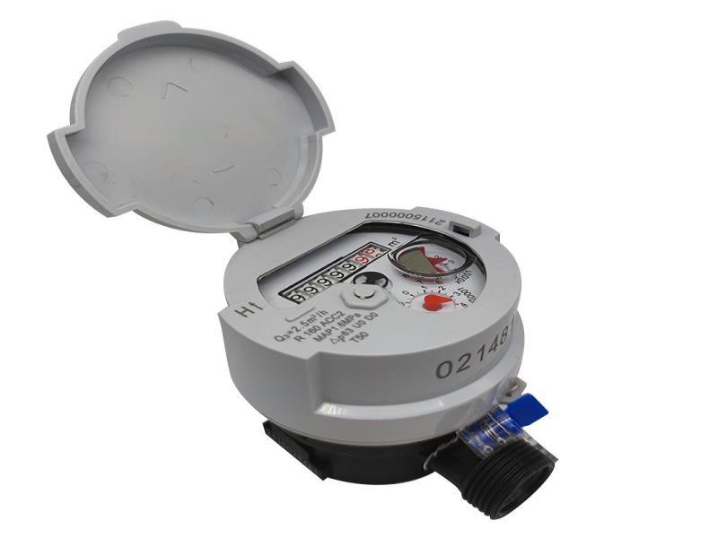
Dimension Diagram (Vertical)
![]()

Dimension
Diameter | Length L | Width | Height | Connection Type | Weight | |
mm | d | D | Kg | |||
Horizontal Installation | ||||||
15 | 165 | 94 | 112.5 | R1/2 | G3/4B | 1.5 |
20 | 195 | 94 | 114 | R3/4 | G1B | 1.8 |
25 | 225 | 98 | 124 | R1 | G1 1/4B | 2.4 |
32 | 230 | 98 | 124 | R1 1/4 | G1 1/2B | 3 |
40 | 245 | 124 | 154 | R1 1/2 | G2B | 5 |
50 | 280 | 165 | 179 | ① | 9.5 | |
Vertical Installation | ||||||
15 | 144 | 98 | 100 | R1/2 | G 3/4B | 1.6 |
20 | 152 | 98 | 100 | R3/4 | G1B | 1.8 |
25 | 164 | 104 | 110 | R1 | G1 1/4B | 2.5 |
① Flange connection according to GB/T17241.6-2008/XG1-2011.
D = ф165, D1 = ф125.
Note: The dimensions and weight are for reference only, and the actual product shall prevail.
Technical Specification
Diameter | Q3/Q1 | Overload Flowrate Q4 | Nominal Flowrate Q3 | Transitional Flowrate Q2 | Minimum Flowrate Q1 | Minimum Reading (Min) | Maximum Reading (Max) |
m³/h | L/h | m³ | |||||
15 | 160 | 3.125 | 2.5 | 25 | 15.6 | 0.00001 | 999999 |
125 | 32 | 20 | |||||
100 | 40 | 25 | |||||
20 | 160 | 5 | 4 | 40 | 25 | ||
125 | 51.2 | 32 | |||||
100 | 64 | 40 | |||||
25 | 160 | 7.875 | 6.3 | 63 | 39.4 | ||
125 | 80.6 | 50.4 | |||||
100 | 100.8 | 63 | |||||
32 | 160 | 12.5 | 10 | 100 | 62.5 | ||
125 | 128 | 80 | |||||
100 | 160 | 100 | |||||
40 | 160 | 20 | 16 | 160 | 100 | 9999999 | |
125 | 204.8 | 128 | |||||
100 | 256 | 160 | |||||
50 | 160 | 31.25 | 25 | 250 | 156.3 | ||
125 | 320 | 200 | |||||
100 | 400 | 250 | |||||
Maximum permission error:
For the lower zone (Q1≤Q < Q2), the maximum permission error is ±5%.
For the upper zone (Q2 <Q≤Q4), the maximum permission error is ±2%.
Performance Features
Temperature Level | T30/T70/T90 | Flow Field Sensitivity Level | U0/D0 |
Pressure Level | MAP10/MAP16 | Accuracy Level | Level 2 |
Pressure Loss Level | Δp63 |
Discover more products in this category
Single-jet Dry Type Water Meter
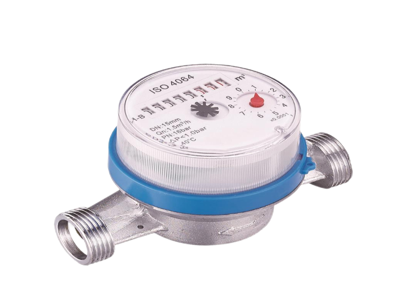
Single-jet Super Dry Cold Water Meter
Single-jet Dry Dial Water Meter
Single-jet Wet Type Water Meter (Brass)